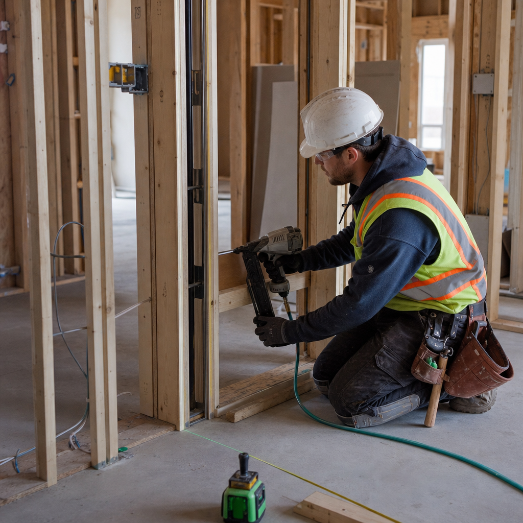
Pocket door systems in Alberta residential construction require intensified attention to structural, code, envelope, and coordination detailing beyond standard swinging doors. On plan sheets, sections, and redline responses, these openings are scrutinized for compliance with the Alberta Building Code (NBC(AE)), local standards, and functional performance-especially within loadbearing, fire-rated, exterior, and high-traffic locations. The intersection of code, dimensioning, construction method, and MEP discipline is brought into sharp focus at each pocket door location on a drawing set.
Structural Detailing for Load Transfer and Lateral Bracing Around Pocket Door Frames
Header Sizing and Load Path Detailing: NBC(AE) 9.23.4.2.
The presence of a pocket door demands strategic changes to wall framing to successfully transfer vertical loads and resist lateral forces. NBC(AE) 9.23.4.2. stipulates clear rules: “The maximum spans and loading for wood lintels (headers) shall be in conformance with the span tables in this Section or with the referenced ‘Span Book.’” Headers over pocket doors are sometimes undersized on drawings, especially when designers default to single 2x4’s in non-loadbearing separations, omitting a code-based check for live/dead loads above the opening.
On plan sets, call-outs such as "2-2x10 SPF #2 HEADER PER CWC SPAN BOOK, U.N.O., SEE STRUCT. DWGS" are placed above the rough opening. Flanking king and jack studs must be scheduled to correspond to the load path shown in the span tables, referencing the wall’s bearing status, storeys above, and point loads from framing above. Where proprietary pocket door kits are used, drawing details must coordinate the kit’s minimum frame requirements with the header and king/jack stud configuration per NBC(AE) 9.23.4.2. and 9.23.10.1.
Stud Configurations: King, Jack, and Cripple Studs
Architectural drafters must indicate a doubled-up king and jack (trimmer) stud at each jamb-"2-2x4 KING + 2-2x4 JACK PER HEADER SCHEDULE"-on the framing plans. Pocket walls, by necessity, lack the typical sequence of in-line vertical studs. Instead, above the header, cripple studs transfer dead and live loads to the header; details must clarify their number, location, length, and fastening as prescribed in NBC(AE) 9.23.5., preventing unsupported top plate segments over the door.
Drafters should show sectional call-outs at pocket walls highlighting king and trimmer studs running full-height, cripple studs spaced as with typical wall construction, and the header bearing on these assemblies. Pocket door kit framing must be dimensioned precisely to the manufacturer's template while honoring code-mandated support around the opening; sheet notes may state "COORDINATE SPLIT-JAMB AND KIT FASTENERS WITH STRUCTURAL FRAMING PER MANUFACTURER AND NBC(AE) 9.23.5."
Blocking for Lateral Stability and Trim Anchorage
The pocket cavity creates a section of wall with drastically reduced lateral stiffness. To mitigate this, horizontal blocking is required at key heights for both lateral stability (particularly in walls susceptible to racking) and for attachment of casing and wall finishes. Details commonly flag horizontal blocking at:
- Top corner of pocket cavity (for drywall attachment and lateral rigidity)
- Mid-height for tall doors or walls over 2435 mm (8’)
- Base of cavity for trim and baseboard anchorage
Illustrating Load Paths and Connections
Sections and details must trace the full transfer path-showing all king, jack, and cripple studs, clear annotation of header type/size, and connections per NBC(AE) 9.23.5. Site crews and plan reviewers rely on these visuals; a missed cripple or ambiguous header is frequently redlined: “Provide header size per NBC(AE) 9.23.4.2.”-“Show king/trimmer stud at jamb, detail fastening." Enlarged framing elevations with “bubble details” (e.g., “SEE DETAIL 4/A4.2”) at each critical connection are standard practice.
Common Plan Review Redlines and Coordination with Proprietary Systems
Code enforcement teams routinely flag drawing sets for:
- Undersized headers at pocket door spans exceeding NBC(AE) Table limits
- Missing or non-continuous king/trimmer studs at pocket cavity jambs
- Lack of blocking leading to “floating” drywall edges or wobbly casings
- Pocket door frame kits called in specs but not coordinated on the architectural-framing/structural sheets
Dimensioning Rough Openings and Detailing on Sheets
On plan and schedule, ROUGH OPENING = DOOR PANEL WIDTH + KIT REQUIREMENTS + CLEARANCE (MIN. 35MM PER MANUFACTURER) is dimensioned. Tags such as “RO: 935 mm (FOR 813 mm DOOR), VERIFY PER KIT” override nominal measurements, preventing field error. All rough opening call-outs are cross-referenced in door schedules, with headers and jamb blocking explicitly scheduled when non-standard. Section marks (“SEE DETAIL 7/A7.2 - POCKET DOOR FRAMING AT LOADBEARING WALL”) are used for wall types at pocket locations, especially where header spans exceed table maximums.
Fire-Rated Pocket Door Assemblies & Continuity of Fire Separations
Pocket Doors in Rated Walls: Certified Assemblies Only
Fire resistance ratings are strictly controlled under Part 9.10 of the ABC. For suite separations or walls adjoining attached garages in Alberta, standard pocket door kits cannot be substituted into a 45-minute or 1-hour FRR wall without an assembly listing. Scope notes and details must specify-"FIRE-RATED POCKET DOOR ASSEMBLY, LISTED TO ULC/UL XX, MIN. 45 MINUTES, MFR: XYZ, PRODUCT: ABC123, INSTALL PER MANUFACTURER AND LISTING".
Assemblies are fire-tested as a system (door+frame+track+hardware). Uncertified substitution, even with fire-rated gyp board, is routinely redlined: “Pocket door in fire separation: Provide listed fire-rated assembly or revise wall construction. Standard kits not permitted (ABC 9.10.13.).”
Continuity of Fire-Rated Gypsum Board in Cavity
Pocket cavities in FRR walls present a discontinuity risk for gypsum board linings. Typical drawings must show Type X gyp board (12.7 mm or 15.9 mm) "RETURNED FULL DEPTH INTO POCKET CAVITY BOTH SIDES, TIGHT TO FRAME, SECURED TO BLOCKING", maintaining the fire barrier without untreated gaps. Enlarged details illustrate:
- Unbroken board extending past the active panel’s slide path
- Sealed joints at header, jambs, and sill
- Continuous application of firestopping at penetrations
Firestopping and Draftstopping: ABC 9.10.13.
Penetrations in fire-separations-created by wall modifications for a pocket-fall under ABC 9.10.13. Firestop products must meet CAN/ULC-S115, installed at every break in continuity whether for the pocket frame, MEP chases, or track. Drawing tags state: “APPLY INTUMESCENT SEALANT (ULC-LISTED) AT ALL POCKET CAVITY-PENETRATIONS-SEE DETAIL 11/A10.5”. Schedules must cite specific materials and locations for firestopping, with listed systems identified by number and agency. Missing or vague firestopping specs are a leading cause of permit delay.
Door Hardware for Fire-Rated Pocket Assemblies
Every component-leaf, track, hardware, closure, seals-requires explicit fire rating. Details must specify:
- Self-closing device at top or concealed in frame (“SELF-CLOSER, CERTIFIED PER DOOR ASSEMBLY UL LISTING”)
- Positive latching (“MIN. 45 MINUTE RATED LATCH SET, UL CERTIFIED”)
- Gasketing around perimeter (“INTUMESCENT EDGE SEAL CONTINUOUS, BOTH JAMBS AND HEADER”)
Redlines and Plan-Review Issues for Fire Integrity
Typical comments for fire-rated pocket door attempts:
- “Unlisted assembly-door/frame/hardware not certified. Revise to listed system.”
- “Gyp board continuity not shown-detail both sides into pocket.”
- “Opening hardware does not latch/self-close-add device per code and listing.”
- “Firestopping not indicated at wall-pocket interface-call out tested system.”
Accessibility and Egress Compliance: Pocket Doors Under Alberta Code
Minimum Clear Opening Widths and Heights: NBC(AE) 9.5.4.3., 9.5.4.4.
Doorways are mandated to provide a clear opening of 810 mm minimum (32”) under Section 9.5.4.3., measured from the leading edge of the fully open pocket door panel to the strike jamb. Key plan note "POCKET DOOR CLEAR OPENING = 810MM MIN. PER NBC(AE) 9.5.4.3. - VERIFY IN FIELD" is standard. Door schedules must distinguish “CLEAR OPENING (DOOR POCKETED)” width from panel size. Section 9.5.4.4. sets a clear opening height minimum of 1980 mm; both dimensions are labeled in enlarged plan or elevation views at “unconventional” openings subject to field adjustment.
Non-compliant clear widths (“Door D22: only 750 mm clear-revise to 810 mm min. per 9.5.4.3.”) are routinely flagged in plan review, especially for ensuite and laundry access.
Operable Hardware: Lever Handles and Flush Pulls - NBC(AE) 9.5.10.2.
Section 9.5.10.2. requires that door hardware “be operable with a closed fist or loose grip” and be mounted “between 900 mm and 1100 mm above finished floor.” On sheet, this is dimensioned with call-outs such as “FLUSH PULL, D-TYPE, CENTERLINE 1000MM A.F.F. PER NBC(AE) 9.5.10.2.” The specification of flush pulls over standard round or recessed types-where insufficient grip or pinching is needed-should be explicit in detail notes and door schedules.
Common plan review comments include: “Revise door pull; round style not closed-fist operable. Use lever or D-pull per NBC(AE) 9.5.10.2." Missing or incorrectly mounted hardware is also redlined: “Hardware center too low/high; must be 900-1100mm above F.F.E."
Flush Floor Transitions at Thresholds: NBC(AE) 9.8.7.4.
Change of level at pocket door thresholds may not exceed 13 mm (1/2"), and must be beveled 1:2 or less. Enlarged threshold details on sheet show “FLUSH TRANSITION, MAX. 13MM DIFF. @ DOORWAY, BEVEL SLOPE ≤ 1:2, NBC(AE) 9.8.7.4.” Floor schedule tags specify compatible finish transitions (e.g., “VINYL PLANK TO TILE, SCHLUTER BEVEL TRIM #E135”). When overlooked, reviewers comment: “Detail floor transitions - trip hazard if not shown 13mm max. and beveled per code”.
Maneuvering and Access Clearances
While the Alberta code does not mandate explicit maneuvering clearances, best practice incorporates suggestions from the AAB: 1500 mm clear on pull side, 1200 mm push side (noted in plan as “recommendation, not code requirement”). Enlarged plans annotate hatched “ACCESS CLEAR ZONE”-especially for barrier-free suites custom built or where client requests universal design.
Common Redlines and Revisions
Frequent reviews yield these markups:
- Insufficient door width: “Revise to provide 810 mm clear opening as per Section 9.5.4.3.”
- Incorrect hardware: “Flush pull to be lever or D-type, operable with closed fist.”
- Threshold hazardous: “Show floor transition detail - threshold must be flush or beveled, max. 13 mm.”
Drawing-Sheet and Detail Conventions
Door schedules list CLEAR OPENING WIDTH/HEIGHT, HARDWARE TYPE + HEIGHT, THRESHOLD DETAIL. Drawings reference enlarged plans (“DETAIL 6/A6.1 - POCKET DOOR ACCESSIBILITY”) for accessibility-critical locations. Elevation views annotate hardware and transition heights: see e.g. “CL FLUSH PULL @ 1000 MM AFF”.
MEP Coordination Within Pocket Door Walls
Electrical: CEC Routing and Shallow Boxes - Referencing ABC 9.34.2.2.
The pocket cavity leaves as little as 38 mm net thickness between split framing-insufficient for standard electrical boxes. ABC 9.34.2.2. aligns with the CEC to require outlets/switches either installed in suitable wall locations or in shallow boxes that do not impede the pocket door’s travel. Plan overlays tag these as “SHALLOW ELECTRICAL BOX (21 MM DEEP), NMD90 CABLE, OFFSET 450MM FROM POCKET CAVITY”. Floor plans clearly relocate switches to adjacent walls, marked “SWITCH RELOCATED, POCKET DOOR INTERFERENCE.”
Plan reviewers commonly note: “Remove electrical outlets/switches from pocket door wall per CEC/ABC 9.34.2.2.” or “Box depth interferes with pocket-detail shallow type.” Coordination sections-cut through the pocket wall-diagram the clearances for MEP services outside the pocket assembly envelope.
Plumbing: Rerouting to Avoid Pocket Cavities - NBC(AE) Part 7
No plumbing-supply, DWV, or vent-may be routed in a pocket door wall, as the requirement for cavity space is absolute. Plumbing risers for sinks, laundry, or hose bibbs must be rerouted to adjacent walls, detailed as “3/4” PEX SUPPLY OFFSET TO ADJ. WALL, POCKET DOOR RESTRICTION”. Sectioned plans or riser diagrams show the displacement of plumbing out of pocket zones, preventing field mistakes such as “shadow pipes” blocking door travel.
HVAC: Ductwork Planning Around Pocket Walls
HVAC returns, supplies, and chases must likewise avoid the pocket cavity. Duct plan overlays designate “NO DUCTING IN POCKET WALL (HATCHED RED)-ROUTE HORIZONTALLY OVER HEADER OR DROP BELOW” and schedule vertical chases immediately adjacent if needed. Sectional details illustrate HVAC transitions around the header or base of the wall without entering the pocket volume.
Overlay and Sectional Detailing for MEP Clearance
Enlarged sections (e.g., “DETAIL 12/M4.1 - MEP CLEARANCE AT POCKET DOOR”) explicitly show dimensional clearances between structural, MEP, and pocket frame kit. Coordination overlays-used at plan review and in field orientation-ensure zero overlap. Typical review comments include: “Verify no MEP conflicts at pocket-show enlarged section, relocate as needed.”
Vapour Barrier Continuity and Moisture Management in Envelope Walls
Vapour and Air Barrier Detailing: NBC(AE) 9.25.3. and 9.25.4.
Exterior walls, and any wall between conditioned/unconditioned spaces (e.g., house-garage) with a pocket door, require rigorous continuity of the air (Section 9.25.3.) and vapour (Section 9.25.4.) barrier systems. Sheet details call out:
- Polyethylene vapour barrier (6MIL POLY VB, PERMEANCE ≤ 60 NG/(PA·S·M²), TO CAN/CGSB-51.34-M), continuous behind and within pocket frame
- Air barrier membrane lapped and taped at all overlaps, joints wrapped tightly around framing and sealed with acoustical mastic-call-out: “VB/AB LAP AND SEAL TO HEADER, JAMB, SILL - ALL EDGES TAPED, ACOUSTICAL SEALANT CONT.”
Wet Area Pocket Doors: High-Humidity Detailing and Materials
Pocket doors in bathrooms and laundry must address moisture exposure. NBC(AE) 9.29.2.2. requires moisture-resistant materials for finishes in “areas subject to frequent wetting.” Call-outs specify:
- MOISTURE-RESISTANT GYPSUM BOARD (e.g., DensShield, or equivalent)
- PVC/VINYL WRAPPED SPLIT-JAMB BLOCKING
- PRESSURE-TREATED LUMBER OR GALVANIZED METAL STUDS at all pocket framing within wet zone cavities
Envelope Penetration and Hardware Protection
To maintain performance, schedule the following protections:
- Flashing above header, lapped at least 100 mm over air/vapour barrier at all exterior walls ("Install peel & stick membrane flashing, min. 100mm lap")
- Continuous drainage plane behind exterior finish, sloped to shed water past pocket hardware
- Drainage slot or vent opening at bottom of pocket wall where hardware exposure is unavoidable
Standard Call-Outs and Plan-Review Corrections for Envelope Issues
- “Show vapour barrier continuity through pocket frame (ABC 9.25.4.).”
- “Seal and tape all AB/VB joints at pocket door; call out method and material.”
- “Specify moisture-resistant finishes if pocket door in high humidity area (9.29.2.2.).”
Conclusion
Integrating pocket doors in Alberta residential architecture challenges drafters and builders to precisely coordinate structure, fire integrity, egress, MEP, and building envelope detailing according to clear code requirements and permit reviewer expectations. Each project sheet must communicate not only the “what” but the “how”-from header sizing and fastening to envelope barriers and moisture management-and anticipate the review process that upholds safety, accessibility, and durability. The result: pocket door installations that pass plan checks, reduce site friction, and deliver enduring performance. Kingsway Drafting & Design elevates Alberta homes through drafting expertise that translates code and construction synergy directly onto every plan sheet.