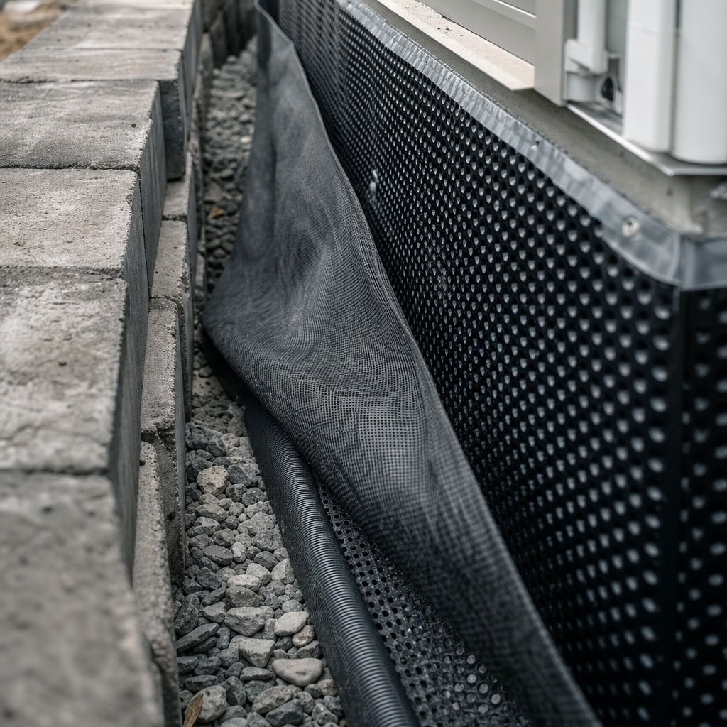
Where retaining walls adjoin basement foundations in Alberta, integrated drainage and waterproofing details are among the most heavily scrutinized aspects of permit plans, plan review, and on-site inspection. As of October 7, 2026, the National Building Code - 2023 Alberta Edition (NBC(AE)) governs these assemblies with exacting prescriptions for membrane selection, overlaps, granular backfill, insulation, drainage pipe systems, and the coordination of all interfaces in the construction drawings. The effectiveness of these assemblies in resisting infiltration, frost, and hydrostatic pressure depends on careful drafting and specification, with particular attention to cross-referencing, dimensioned extents, and material compatibility.
Below-Grade Waterproofing Membrane and Protection Board Detailing at the Retaining Wall-Foundation Interface
ABC 9.13.1.2, 9.13.2.1-4: Membrane Requirements, Overlaps, and Continuity on Plans
Under ABC 9.13.1.2, dampproofing is mandatory for all exterior foundation wall surfaces below ground level where hydrostatic pressure is not expected but the finished ground level outside exceeds the interior. The requirement expands to full waterproofing-including continuity across interfaces and at all wall junctions-when groundwater with hydrostatic pressure is present per 9.13.3.1. Specifications are often verified against standards such as CAN/CGSB-37.2-M or CAN/CSA-A123.4 for membranes, noted both in general notes and in specific elevation or section call-outs.
Membranes must be detailed to wrap seamlessly around corners-between main foundations and adjoining retaining walls-with no voids, unsupported joints, or abrupt terminations. On plan sheets, section tags such as DETAIL 7/A-601 "RETAINING-FDN INTERFACE" should be used at every junction. Keynotes commonly read: “CONTINUOUS SELF-ADHERED SBS MODIFIED BITUMEN MEMBRANE, MIN. 1.5mm THICK, EXTENDED 150mm UP RETAINING WALL AND OVER FDN WALL TO 150mm BELOW TOP OF WALL. OVERLAY ALL LAPS 100mm MIN. WITH FACTORY-APPROVED PRIMER AT COLD JOINT.”
Protection Board Fastening and Plan-Review Redlines
Protection boards-typically 19mm+ extruded polystyrene (XPS) or heavy-duty fibrous mat-must lie directly against the membrane to protect from damage during backfilling. NBC(AE) reviewers frequently flag “PROTECTION BOARD FASTENING BY MECH. CLIPS PENETRATES MEMBRANE, PROVIDE ADHESIVE ATTACHMENT, TYP.” The use of adhesives compatible with the specific membrane system is critical; this must be noted in both the assembly keynotes and enlarged wall sections (eg: ADHERE PROTECTION BOARD TO MEMBRANE, DO NOT FASTEN THROUGH WATERPROOFING). Board extents are dimensioned on sections: “PROTECTION BOARD CONTINUOUS FROM FOOTING TO 200mm BELOW GRADE, TYP. BOTH SIDES OF INTERFACE.”
If interface continuity is ambiguous, reviewers remark: "MEMBRANE TERMINATION NOT SHOWN AT INTERFACE-DETAIL REQUIRED, SEE REDLINED SHEET A502. PROVIDE ENLARGED SECTION SHOWING CONTINUOUS MEMBRANE WRAP WITH NO VOID AT FOUNDATION-RETAINING WALL JUNCTION." Enlarged details should show the membrane turning up onto the intersecting wall, lapped and primed as per manufacturer's guidelines, and termination bars used at exposed edges (eg: top of wall, slab step, or grade beam).
Material Specs, Thicknesses, and Drawing Sheet Call-Outs
Standardized hatch patterns and designations, such as a heavy, dashed fill for “SBS MODIFIED BITUMEN MEMBRANE, 1.5mm MIN.”, are coupled with wall tags referencing both material and code:
- "APPLY SBS MEMBRANE TO EXTEND 150mm UP RET. WALL; LAPS 100mm MIN., APLIC'N PER 9.13.2.2(4)(b)"
- "19mm XPS PROTECTION BOARD OVER MEMBRANE; ADHERE INLINE, CONT. TO 150mm BELOW GRADE"
Material schedules and legend boxes are used on the overall wall sections and detail blowups. All plan sheets must explicitly indicate membrane, overlap, and termination points on both horizontal and vertical cuts.
Dimensioning and Detailing the Perforated Drain Pipe and Granular Backfill System
ABC 9.14.3.1-4: Pipe, Granular Fill, and Filter Fabric in Construction Documents
NBC(AE) 9.14.3.1-4 codifies perimeter foundation drainage systems, including retaining walls that tie back to occupied basements. Pipes must be min. 100mm dia. (commonly called out as “100mm PERF. PVC PIPE, CSA B182.1”) and set in min. 150mm clean washed gravel (“19mm DRAIN ROCK, <10% FINES, EXT. 150mm ALL SIDES”). Sectional call-outs like DETAIL 14/S-402 “PERF. DRAIN TILE BELOW RET. WALL” typically graphically separate drainage at the base of the retaining wall from that at the foundation footing, but connect systems in a continuous “racetrack” loop or with explicit connections to the main foundation sump or storm lead.
Invert Elevations, Slope, and Connection Detailing
Alberta plan reviewers often cite missing slope dimensions and invert elevations: "FOUND. DRAIN SLOPE UNDIMENSIONED; PROVIDE 2% MIN. = 20mm/M SLOPE TO OUTLET/CONN. POINT (9.14.3.3(4))." Plan sheets must dimension both starting and terminating invert elevations at key points-ie: “INV. @ SOUTHEAST RETAINING WALL 103.40, SLOPE 2% TO FDN SUMP AT 103.15, PROVIDE AS-BUILT SPOT CHECK.”
Filter fabric-clearly shown as a light, dashed hatch or a distinct filter wrap notation (“NON-WOVEN FILTER FABRIC, 150g/m², TYP. OVER GRAVEL, 9.14.4.2(2)”)-is called out to wrap both above and below the granular backfill, with minimum lateral cover specified (eg: “EXTEND FABRIC 300mm BEYOND PIPE EACH SIDE, LAP MIN. 150mm AT ALL JOINTS.”)
Section Call-Outs and Material Specifications
Sectional details are dimensioned as follows, referencing not only code but ASTM/CSA standards:
- “100mm Ø PERF. PVC DRAIN PIPE ON 150mm 19mm WASHED GRANULAR BASE, COVER ALL SIDES MIN. 150mm, WRAP IN FILTER FABRIC PER 9.14.4.2, SLOPE 2% MIN. TO SUMP.”
- “SEE DTL 04/S-401 FOR GRANULAR & DRAIN PIPE LAYOUT UNDER RET. WALL FOOTING; NOTE INVERT RELATION TO FDN DRAIN, TYP.”
When multiple wall heights or stepped foundations are present, sheets must include “STAIR STEP” or “SPLIT FOOTING” details, showing pipe transitions, crushed rock placement, and fabric continuity with explicit breaklines and notes.
Redlines emerge if: “GRANULAR BACKFILL SPEC NOT SHOWN; NOTE ‘19mm WASHED GRAVEL <10% ON #4 SIEVE’ EVERY SECTION”, or “PIPE SIZE <100mm; REVISE TO MIN. 100mm PVC PERF. DRAIN”. Adherence to these code-mandated minimums is non-negotiable for sign-off.
Hydrostatic Pressure Relief and Frost Protection at the Retaining Wall-Foundation Junction
ABC 9.13.3.1, 9.14.2.1, 9.15.2.1: Detailing Drainage Composites and Insulation for Alberta's Climate
Foundation design must address both water and temperature: 9.13.3.1 requires explicit waterproofing where hydrostatic conditions prevail, while 9.14.2.1 prescribes drainage at all wall bottoms, and 9.15.2.1 defines minimum concrete compressive strength and freeze-thaw resilience. These elements converge at retaining-foundation wall junctions, demanding fully integrated construction details on the plan set.
A typical sectional detail (REFER TO DTL 11/A-705 “HYDROSTATIC RELIEF & FROST PROTECTION, TYP.”) combines:
- Vertical drainage board-19mm min. “dimple mat” or two-layer prefabricated composite with flow capacity >0.5 L/s/m²-continuously from top of footing to min. finished grade, lapped at 100mm with mastic-sealed termination at wall top (keynote: “VERT. DRAIN MAT, 19mm, EXT’D FROM FOOTING TO GRADE. LAP 100mm AT ADJOINING SECTIONS; FLUID-APPLIED SEAM SEALANT @ LAPS.”)
- Rigid insulation (XPS or comparable)-min. R-10 (as per multiple STANDATA clarifications for frost depth in central/southern Alberta)-extending vertically from footing to 600mm above grade, and horizontally from face of retaining wall out minimum 900mm, thickness dimensioned and tagged “50mm XPS R-10 MIN. FROST PROTECTION TO EXCEED LOCAL NAT’L FROST DEPTH REQUIREMENTS (SEE 9.15.4), ALL INSULATION STAGGERED & SEALED.”
Joints, particularly where the retaining wall steps or abuts the main foundation, require blow-up details with insulation and drainage mat continuity shown. Material schedules call out compressive strengths (XPS: 300 kPa min.) and identify all fasteners and sealants. Where rigid insulation extends above grade, plans show protective parging or coated finish to UV-exposed surfaces.
Typical Plan-Review Redlines at this Junction
Plan reviewers in Alberta routinely mark:
- “INSULATION EXTENT AT CORNER/STEP NOT SHOWN; PROVIDE DETAIL DIMS BOTH VERT & HORIZ TO 900mm MIN.”
- “DRAIN MAT TERMINATION UNCLEAR-SHOW CONTINUITY ACROSS FDN-RET. WALL JUNCTION, TIE TO FDN DRAIN.”
- “NO COMPRESSIVE STRENGTH FOR INSULATION-SPEC 300kPa XPS MIN.,” or “DKT DRAIN MAT/FABRIC COMPATIBILITY NOT NOTED; ADD GENERAL NOTE.”
Integration of all materials at the interface must include explicit notes and diagrams: “CONT. MEMBRANE, INSULATION & DRAIN MAT; SEAL AT CORNER WITH FLUID-APPLIED FLASHING, TYP. FOR ALL TURNS.”
Plan-Set Sheet Organization and Annotation for Drainage/Waterproofing
ABC 9.1.1.2 & Professional Practice Sheet Conventions
Alberta Building Code 9.1.1.2 requires construction documents be “clear, complete, and accurate.” Staging of waterproofing and drainage details across the plan set must facilitate both construction sequencing and compliance verification.
Site plan sheets illustrate overall grading-proposed spot elevations and 200mm over 2m min. slope away from foundations, with:
- Call-outs such as “FIN GRADE SLOPE AWAY FROM FDN, 2.0m @ 10%, 200mm DROP, PER 9.14.3.1”
- Spot elevation tables and contour callouts for “EXIST’G” and “PROPOSED” grades at corners, midpoints, and all critical egress
- Directional arrows for overland surface drainage, at every major retaining/foundation interface
General notes are centrally listed (“ALL WATERPROOFING AND DRAINAGE INSTALLATION TO MEET NBC(AE) 9.13, 9.14, AND LOCAL BYLAW REQUIREMENTS”). Keynotes reference all enlarged details (“SEE DTL 3/A-601 FOR TYP. MEMBRANE AT RETAINING-FOUNDATION JUNCTION”).
On wall section sheets, every waterproofing, insulation, and drainage element is both dimensioned and cross-referenced (“SEE SCHED. A FOR MATERIAL SPECS AND MANUFACTURER APPROVAL”; “SEE DTL 8/S-402 FOR TYP PIPE/GRANULAR SECTION”). Labels such as “WEEPING TILE TIED TO MAIN FDN SUMP” or “RET. WALL FDN @ 103.33 INVERT, SLOPE 2% MIN. SHOWN” must be both readable and corroborated with enlarged blow-up details.
Cross-Referencing, Keynotes, and Plan-Review Triggers
The use of robust, unique detail identifiers (eg: 7/A-601; 11/A-705) allows both code reviewers and contractors to cross-check material extents, overlap locations, drainage line inverts, and all interfaces. Keynotes are attached to both plan and section, eg:
- “NOTE 12: CONT. SBS MEMBRANE WRAP, LAP 100mm MIN., NO INTERRUPTIONS AT RETURNS/JUNCTIONS.”
- “NOTE 17: 19mm XPS, ADHERE TO MEMBRANE, EXTEND VERT. & HORIZ. AS PER DETAIL 5/A-602.”
General notes reinforce construction QA/QC, such as:
- “ALL MEMBRANE TERMINATIONS TO BE LAP-JOINTED AND SEALED WITH MANUFACTURER-APPROVED PRIMER.”
- “ALL DRAIN PIPE CONNECTIONS TO FDN SYSTEM TO BE INSPECTED PRIOR TO BACKFILL.”
- “ALL BELOW-GRADE PENETRATIONS TO BE SEALED WITH ELASTOMERIC SEALANT COMPATIBLE WITH SBS MEMBRANE.”
Plan-reviewers frequently flag plans lacking explicit cross-referencing, writing “DETAIL REFERENCE MISSING FOR CRITICAL DRAINAGE ASSEMBLY-ADD ENLARGED SECTION AND SCHEDULE REFERENCE.” and “SLOPE & INVERT TO BE TAGGED AT EACH SYSTEM JUNCTION-SEE REDLINED GRADING SHEET.”
Detailing Critical Connections: Downspouts, Window Wells, and Below-Grade Penetrations
Downspouts: Integration with Site and Subsurface Drainage
Surface runoff from the roof is not solved by downspouts alone; discharge must be detailed to direct water well away from vulnerable foundation areas. While the NBC(AE) does not prescribe explicit downspout dimensions, best practice calls for 75x100mm (3"x4") downspouts extended a minimum of 1.2m (4'-0") from the foundation by rigid extensions or splash pads. Site plans and elevations both tag locations with symbol and keynote; plan call-outs must state: “DOWNSPOUT DISCHARGE 1.2m MIN. FROM FDN, GRADE TO SLOPE AWAY, PER CALGARY BYLAW & NBC(AE) 9.14.”
For site configurations with tight lots or walks, notes direct the installer: “IF 2.0m EXTENSION NOT POSSIBLE, PROVIDE APPROVED SPLASH PAD & GRADE TO DRAIN TO FRONT/REAR/SIDE YARD, NOT PUBLIC WALK”; redlines appear if downspouts terminate without explicit grading direction.
Window Wells: Sizing, Drains, and Waterproofing Interface
NBC(AE) 9.14.6.3 is explicit: every window well must drain to footing or other suitable location, never remain unconnected. Standard residential window wells are dimensioned on plans and detail sections as minimum 760mm (30") out from wall, 150mm (6") clear beyond window, 300mm (12") below the sill. All detail callouts reinforce this:
- “WINDOW WELL: 900 x 1200 x 600mm DEEP, EXTEND 300mm BELOW SILL, INFILLED WITH 19mm CLEAR STONE, <10% FINES, FILTER FABRIC ENVELOPE, 100mm PERF. PVC WELL DRAIN AT BASE SLOPED TO FDN TILE SYSTEM @ 1% MIN.”
- “WELL TO PROJECT 100mm MIN. ABOVE FIN. GRADE, FLASH WATERPROOF MEMBRANE OVER OPENING LAP 100mm.”
Redlines flag any omission, eg: “WINDOW WELL DRAINAGE METHOD NOT SHOWN; ADD TIE-IN TO FDN DRAIN @ BASE.” Schematic plans use a distinct window well symbol, cross-referenced to an enlarged section (5/A-603) and tagged in window, foundation, and grading schedules.
Below-Grade Penetrations: Waterproof Sealing and Drainage Integration
Penetrations such as utilities through foundation or retaining walls demand expanded detail envelopes, with notes such as:
- “PVC SLEEVE, 100mm, GROUT-FILLED ANNULAR SPACE, WATERSTOP COLLAR NEXT TO FDN WALL, FLUID-APPLIED ELASTOMERIC SEALANT BOTH SIDES. WATERPROOFING MEMBRANE LAPPED AND SEALED 150mm ALL SIDES.”
Drawing sheets explicitly tag these assemblies (eg: SEE P-105 FOR TYP. BELOW-GRADE PIPE PENETRATION DETAIL). Notes require non-penetrating fasteners; if any through-bolt is required, double-o-ring flanges and sealant beads must be dimensioned. Filter fabric and drain mat must be detailed to tuck tight to the sleeve and integrate with other drainage assemblies.
Common review comments include:
- “PENETRATION SEALING METHOD NOT SPEC’D; ADD SHEET/DETAIL REFERENCE AND CLARIFY SEQUENCE.”
- “NO DRAINAGE BOARD RETURN AT SLEEVE-PROVIDE L-SHAPED MAT DETAIL, ADHERE ALL EDGES.”
Unified Drawing and Specification Practices to Avoid Redlines
Across all these critical connections, the standard for plans in Alberta is a combination of plan, section, and blown-up axonometric detail: every interface cross-referenced via keynotes; every material and sequence dimensioned, with code section/pathways notated. The design schedule must report every material type, thickness (membrane, insulation, protection board), fastening or adhesion method, required overlap or lap, and pipe invert. All required STANDATA/municipal bylaw details that modify standard code are boxed out in “Supplementary General Notes”.
Conclusion: Coordinated Detailing for Integrated Performance
Integrated drainage and waterproofing detailing at the junctions of retaining walls and basement foundations in Alberta is a rigorously code-governed, construction-sequenced process. The clarity and quality of dimensioned plans, cross-referenced details, annotated call-outs, and comprehensive specification schedules are what separate a smooth permit submission and on-site QA from cycles of costly redlines, change orders, or post-backfill failures. In every case-whether at a sheet edge, a window well, or a below-grade sleeve-construction drawings must not simply “show intent,” but provide a granular, code-backed script for building in Alberta’s challenging climate.
For advanced drafting, review, or custom detail development to meet code, municipality, and builder requirements in Alberta, Kingsway Drafting & Design delivers full-spectrum residential construction documentation.